This build project was published on ARSI Ham Radio News 2018 Q4 edition
Please check it out.
Kiran VU2XE
Wednesday, October 10, 2018

Thursday, September 27, 2018
Low Pass Filter(LPF) and Application in Amplifiers
Recently I came across few comments on whether LPF is really required for Solid State Amplifiers.
I am no professional or expert in this area, however, my W6PQL amplifier built has taught me something to state here.
Any solid state design has some non linearity and thus introducing harmonics. Harmonic distortions are main reason why one hears spatter on few bands even when other parameters are conducive for HF. There are regulations in some part of the world to keep such distortions limited to lower than -40dB. It does not matter what power we are running, we need to keep this as a best practice guideline and make things better for all others on the band.
If you have an amplifier for 1 to 7Mhz, having one LPF for 7Mhz band is not sufficient for operating the amplifier on 160mtr and 80mtr. We have second and third harmonic of 160mtr falling in pass band range of 7Mhz LPF. Similarly second harmonic of 80mtr falls in 7Mhz. So essentially such LPF will only be good for operating 7Mhz band (where its harmonics are on 20 and 15Mtrs will be filtered).
Next time someone says amplifier works well because of its efficiency etc. Also pause and talk about signal purity and distortion characteristics. No modern solid state amplifier is complete without LPF sections to cover each band of its operating frequency. Else you might be splattering all over other bands even with 100 watts of power output on fundamental operating frequency!.
Spending some time on understanding these aspects will keep us serene on the bands :)
VU2XE
Kiran
I am no professional or expert in this area, however, my W6PQL amplifier built has taught me something to state here.
Any solid state design has some non linearity and thus introducing harmonics. Harmonic distortions are main reason why one hears spatter on few bands even when other parameters are conducive for HF. There are regulations in some part of the world to keep such distortions limited to lower than -40dB. It does not matter what power we are running, we need to keep this as a best practice guideline and make things better for all others on the band.
If you have an amplifier for 1 to 7Mhz, having one LPF for 7Mhz band is not sufficient for operating the amplifier on 160mtr and 80mtr. We have second and third harmonic of 160mtr falling in pass band range of 7Mhz LPF. Similarly second harmonic of 80mtr falls in 7Mhz. So essentially such LPF will only be good for operating 7Mhz band (where its harmonics are on 20 and 15Mtrs will be filtered).
Next time someone says amplifier works well because of its efficiency etc. Also pause and talk about signal purity and distortion characteristics. No modern solid state amplifier is complete without LPF sections to cover each band of its operating frequency. Else you might be splattering all over other bands even with 100 watts of power output on fundamental operating frequency!.
Spending some time on understanding these aspects will keep us serene on the bands :)
VU2XE
Kiran
Monday, May 28, 2018
Terrain Analysis matters ! - Correlation to Contest Scores
Couple of years ago my neighbourhood started changing rapidly. Once used to be a 5 Acre coconut grove just 100 Feet north of my QTH was grounded over a week's time. It is the demolition monster drive similar to the one in Avataar movie. Along with hundreds of eagles and birds who lost their home that day, I had lost hope on my peak DXing days! After hearing that it was mega project with 360 apartments spread over 5 blocks of 18 floors each, my spinal felt like just out of frozen ice :(.
One of my senior ham friend did help me morally a bit providing what was unknown to me then called HFTA. That analysis stated that, I will loose my sight in the direction of this building which is 320 deg to around 30 Deg north. And it happens to be prime area for contesting and DXing over the poles!.
Recently I purchased ARRL's Antenna handbook. The CD which came with it contained HFTA software written by N6BV. I got hooked to it once I learnt how to use it. It opened up new paradigm for me on HF ray propagation and study the effect of stacking, antenna height with respect to immediate terrain. In combination with K6TU.net 's excellent terrain data service. I started doing many hours analysis of locations I had been recently as well.
CQWPX CW 2018 was the first contest after the high rise got completed. This contest was to test my understanding and vola... It really did reflect what was predicted. Signals were way down than it used to be. Partially overall HF weather also had a play I am sure.
Following are the graphs of these changed conditions. My terrace is at 140 ft level and around 150 ft from me is 180 ft tall building.

I plotted the graph with antenna at popular 50ft level on flat reference ground(Green), 150Ft level without the highrise (Blue) at 330 deg and current condition with Highrise (Red). Purple bars show %ge times signal arrival based on statistics.
We can see at 150ft level, there were deep nulls with signals below reference level. But then, there was surge in gain at low angles. No wonder why I used to catch K3LR and other long haul DX before many could hear them. But see what happened to me now. Red line barely rises above reference and gain is no where near compared to peak gain of 16dbi at 7 Deg I had earlier (down by 15 dBi now i.e 2.5 SUnits or more). Less of make and lot of break moments. We can also see that between 3Deg and 13 Deg there is statistical average of 5% or more signal arriving. All these chances are lean now.
Following is similar graph for 15Mtr band.

And this reflected in my score. I used to have restricted grade earlier and best score was in 2015 CQWW CW with nearly a million points. I could achieve this with 2 element Hex and 50Watts only. End of 2017 in the same contest I could only manage 600K points, that too with 400 Watts and Spiderbeam. i.e. effectively 9dB (due to Amp) + 1.5 dBi (avg spiderbeam increase) = 10.5 dBi gain.
This gain in forward direction was negated by the high rise on transmit. On receive it is only 1.5 dBi, which will be of no use as building is blocking most of the low incoming signals. In total effect, i may be sounding similar to my restricted grade signal to DX, but if they respond and signal rays arrive at those angles, I will never hear them :(.
Lastly, 150 Feet height was not the best in both the cases either. One can see deep nulls at some elevation angles with good %ge of signal arrivals. Most of the contesters have mono bander stacks just to overcome those deep nulls. Following is stack of two number of 3 element yagis at 90 and 120 feet. See how it moves the nulls to right making space for desired angles.

Today, I feel I know many of these wonderful areas of propagation due to software such as HFTA, but handicapped to try the improvements. I am hoping that in the future, I can go to right places and put portable stations for contests!
Cheers
VU2XE Kiran
Disclaimer: As usual, this blog and its content is only based on my own personal experiments and observations. I share it for fun and in hope to kinder some curiosity. I am no expert in these areas. Sometimes, my conclusions may not be accurate. For accurate information you are suggested to look out for original sources and experts in these areas.
One of my senior ham friend did help me morally a bit providing what was unknown to me then called HFTA. That analysis stated that, I will loose my sight in the direction of this building which is 320 deg to around 30 Deg north. And it happens to be prime area for contesting and DXing over the poles!.
Recently I purchased ARRL's Antenna handbook. The CD which came with it contained HFTA software written by N6BV. I got hooked to it once I learnt how to use it. It opened up new paradigm for me on HF ray propagation and study the effect of stacking, antenna height with respect to immediate terrain. In combination with K6TU.net 's excellent terrain data service. I started doing many hours analysis of locations I had been recently as well.
CQWPX CW 2018 was the first contest after the high rise got completed. This contest was to test my understanding and vola... It really did reflect what was predicted. Signals were way down than it used to be. Partially overall HF weather also had a play I am sure.
Following are the graphs of these changed conditions. My terrace is at 140 ft level and around 150 ft from me is 180 ft tall building.

I plotted the graph with antenna at popular 50ft level on flat reference ground(Green), 150Ft level without the highrise (Blue) at 330 deg and current condition with Highrise (Red). Purple bars show %ge times signal arrival based on statistics.
We can see at 150ft level, there were deep nulls with signals below reference level. But then, there was surge in gain at low angles. No wonder why I used to catch K3LR and other long haul DX before many could hear them. But see what happened to me now. Red line barely rises above reference and gain is no where near compared to peak gain of 16dbi at 7 Deg I had earlier (down by 15 dBi now i.e 2.5 SUnits or more). Less of make and lot of break moments. We can also see that between 3Deg and 13 Deg there is statistical average of 5% or more signal arriving. All these chances are lean now.
Following is similar graph for 15Mtr band.

And this reflected in my score. I used to have restricted grade earlier and best score was in 2015 CQWW CW with nearly a million points. I could achieve this with 2 element Hex and 50Watts only. End of 2017 in the same contest I could only manage 600K points, that too with 400 Watts and Spiderbeam. i.e. effectively 9dB (due to Amp) + 1.5 dBi (avg spiderbeam increase) = 10.5 dBi gain.
This gain in forward direction was negated by the high rise on transmit. On receive it is only 1.5 dBi, which will be of no use as building is blocking most of the low incoming signals. In total effect, i may be sounding similar to my restricted grade signal to DX, but if they respond and signal rays arrive at those angles, I will never hear them :(.
Lastly, 150 Feet height was not the best in both the cases either. One can see deep nulls at some elevation angles with good %ge of signal arrivals. Most of the contesters have mono bander stacks just to overcome those deep nulls. Following is stack of two number of 3 element yagis at 90 and 120 feet. See how it moves the nulls to right making space for desired angles.

Today, I feel I know many of these wonderful areas of propagation due to software such as HFTA, but handicapped to try the improvements. I am hoping that in the future, I can go to right places and put portable stations for contests!
Cheers
VU2XE Kiran
Disclaimer: As usual, this blog and its content is only based on my own personal experiments and observations. I share it for fun and in hope to kinder some curiosity. I am no expert in these areas. Sometimes, my conclusions may not be accurate. For accurate information you are suggested to look out for original sources and experts in these areas.
Tuesday, May 22, 2018
Multibander antenna and harmonic radiation thoughts
Desclaimer: Articles here are purely based my personal experiments and observations. Though i read lot of articles and books on my favorite subject of Antennas and Propagation, i am no expert in this field. If you are here looking for such accurate information, this blog may not be for you. Otherwise, hope you will enjoy reading these posts and probably try some techniques yourself!
I have been using HF multibander for many years now. My first multibander 40-10m antenna at Mumbai QTH involved simple inverted Vee with single feeder at around 20ft above the apartment terrace. It worked very well giving hours of fun on the band.
I started using tuned magnetic loop for QRP digital modes when I traveled within US. It was simply amazing experience using loops.
When I moved to Bangalore in 2011, my first comeback antenna was Hex beam. It is awesomely portable, and gave value for every bit i spent. It was my sole antenna for couple of years with some experimental wire delta loops, dipole and verticals on the side. Currently, I have Spiderbeam antenna which is another dB upgrade to my station for sure!.
All these times i was not much having thoughts around monoband antennas other than my 40mtr vertical. I had not even considered putting up any serious yagis due to apartment living. Reading a lot about other contest stations around the world, i was wondering why they normally have mono bander stacks. One obvious reason is for stacking antennas with optimal height distances and pattern uniformity. Second reason, i am sure these multi stations aim is for reducing harmonic radiation.
This second aspect, never caught my attention till now. Here is what happens to typical station transmitting with solid state amplifier. Suppose amplifier's LPF section is not working, and fundamental on 40mtr is around 400Watts, second harmonic is 40dB down and third is only 10dB down. Refer https://www.w6pql.com/a_1.5kw_lpf_for_160-6m.htm
15mtr band will see 40W signal for 400W. Without LPF between amp and multiband antenna 40 to 10mtr fan dipole for example, will transmit both 400W fundamental signal and also 40W harmonic signal will be transmitted on the air. This power is more than sufficient to cause QRM. It just sucks!.
Currently my amplifier has LPF board which suppresses the harmonics to greater than -50 dB. That is to teen milliwatt level which brings signals into safe zone. Now going back to multiband antenna again assuming that there was no harmonic suppression, with yagi of 10dB gain, 40W harmonic would sound like 400W signal simulcasting on harmonic band. With resonant monobander this problem is eliminated. In reverse direction it is true for receiving as well, resonant monobander acts like pre selector eliminating any front end related issues and IMD. Whereas, multi bander keeps gate open for all signals resonant on those bands.
This topic started to make me think some field antennas tried in the past by me such as fan verticals and fan inverted Vee, may not be right choice during the contests or in multi station activation.
A point to ponder further and probably test sometime!
Cheers
Kiran VU2XE
I have been using HF multibander for many years now. My first multibander 40-10m antenna at Mumbai QTH involved simple inverted Vee with single feeder at around 20ft above the apartment terrace. It worked very well giving hours of fun on the band.
I started using tuned magnetic loop for QRP digital modes when I traveled within US. It was simply amazing experience using loops.
When I moved to Bangalore in 2011, my first comeback antenna was Hex beam. It is awesomely portable, and gave value for every bit i spent. It was my sole antenna for couple of years with some experimental wire delta loops, dipole and verticals on the side. Currently, I have Spiderbeam antenna which is another dB upgrade to my station for sure!.
All these times i was not much having thoughts around monoband antennas other than my 40mtr vertical. I had not even considered putting up any serious yagis due to apartment living. Reading a lot about other contest stations around the world, i was wondering why they normally have mono bander stacks. One obvious reason is for stacking antennas with optimal height distances and pattern uniformity. Second reason, i am sure these multi stations aim is for reducing harmonic radiation.
This second aspect, never caught my attention till now. Here is what happens to typical station transmitting with solid state amplifier. Suppose amplifier's LPF section is not working, and fundamental on 40mtr is around 400Watts, second harmonic is 40dB down and third is only 10dB down. Refer https://www.w6pql.com/a_1.5kw_lpf_for_160-6m.htm
15mtr band will see 40W signal for 400W. Without LPF between amp and multiband antenna 40 to 10mtr fan dipole for example, will transmit both 400W fundamental signal and also 40W harmonic signal will be transmitted on the air. This power is more than sufficient to cause QRM. It just sucks!.
Currently my amplifier has LPF board which suppresses the harmonics to greater than -50 dB. That is to teen milliwatt level which brings signals into safe zone. Now going back to multiband antenna again assuming that there was no harmonic suppression, with yagi of 10dB gain, 40W harmonic would sound like 400W signal simulcasting on harmonic band. With resonant monobander this problem is eliminated. In reverse direction it is true for receiving as well, resonant monobander acts like pre selector eliminating any front end related issues and IMD. Whereas, multi bander keeps gate open for all signals resonant on those bands.
This topic started to make me think some field antennas tried in the past by me such as fan verticals and fan inverted Vee, may not be right choice during the contests or in multi station activation.
A point to ponder further and probably test sometime!
Cheers
Kiran VU2XE
Saturday, April 14, 2018
Troubleshooting RFI with SDR Play USB cable
DESCLAIMER
– This writeup or any other articles I share are purely my practical observations/experiences
and do not claim authority on the subject. It is upto reader’s discretion to consider
its value as applicable in similar situations. For accurate, scientific and authoritative
expert knowledge, you are strongly encouraged to seek books, professionals and experts
in the subject.
Introduction:
Most of us one time or other observed RFI issues. There
could be various reasons due to which RFI is observed such as unfiltered SMPS, electrical
arching on the poles, harmonic generated by the amplifiers etc. There may be
considerable unwanted RF floating via Coax shield due to imbalance near the
antenna load feed point as well. Coax shield’s current issue is mostly solved
by common mode chokes. Whether in the form of ugly BalUn (length of coax wound
as a coil near the antenna) or ferrite beads placed on coax or Coax wound on
toroid etc. There is a wealth of information available on website nowadays and
can be easily accessed. Couple of excellent references are mentioned towards
the end of this article.
Intent of this article is to share another angle of RFI
within one’s shack, and my own experience in resolving the RFI for my SDRPlay receiver
interfaced with Kenwood TS590.
For sometime now, I have been using with SDRPlay
receiver along side with TS590 transceiver. I had done a simple mod
for TS590 to tap RX only output and feed it to SDR. Though it works very well
as panadaptor and additional receiver capability taking advantage of TS590’s internal
TRX switching, I had always found that panadaptor showing strong presence of RF
when transmitting on TS590. This was the
fact event when SDR was not connected to the RX port. Stray RF in the shack for
sure was causing some issues.
Setup:
- Kenwood TS590 with RX out mod
- BufferAmp from Clifton lab Z10000
- NKK dummy load
- SDRPlay RSP1 SDR receiver
- HDSDR software with Omnirig synchronization
Equipment layout for testing:

Following is how I figured out the root cause:
Step 1. Removed coax between TS590 RX Buffer amp out to
SDRPlay – No change observed
Step 2. Shorted SDR’s RX antenna input SMA port – No change
observed
Step 3. Placed SDR Play inside aluminum box – No change
observed
Step 4. Distanced USB cable of SDRplay from any other shack
cable – change observed as distance increased from computer and other equipments
Step 5. Wound SDR’s USB cable few times on Toroid of 43 mix.
Saw a noticeable change in SDR display. So stray RF is entering via USB cable
to SDR’s circuitry for sure. I continued with changing number of turns on the
toroid, changing the bands and changing the mixes etc.
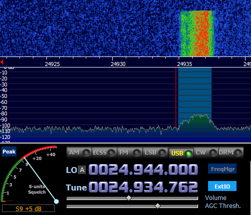
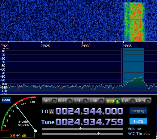
Following are the further snapshots of various band observations
with actual snapshots from HDSDR.
Band
|
8 Turn Mix 31 (240-31)
|
8 Turn Mix 43
(240-43)
|
8turn each Mix
31 and Mix 43 in series
|
160m
|
 |
 |
 |
80m
| Not tested | ||
40m
|
 |
 |
 |
20m
|
 |
 |
 |
15m
|
 |
 |
 |
12m
|
 |
 |
Not tested
|
10m
|
 |
 |
 |
Conclusion:
Above pictures explain what cores were working for the
situation. I could not do very accurate test of audio signal as I was not using signal generators. As per my observation 31 Core and 43 behaved similarly at first sight. At lower bands, I could see tiny to some differences. However, as we moved to higher bands, 43 had slight edge. on 12 mtr and 10 mtr combination of 31 mix core and 43 mix core worked better. I didn't had 61 mix core at hand. I understand that they works better at those bands.
Many a times some of us constraint ourselves thinking that aspects
of the hobby are highly technical in nature. Though it is so, for the real seeker
and ham who wants to advance to next level, it cannot be a bottleneck. I
have not touched subject of measurement of complex impedance, phase, permeability,
power saturation etc. though I know a very little in the area, it is still a
bouncer for me and also not the intent. It is all about learning, applying it
to practice and sharing what worked!.
Hope this helps someone in similar situations.
73
DE VU2XE Kiran
Further References:
Sunday, March 11, 2018
Stack it Up! - Experiment during ARSI National Field Day
As part of National Field Day/ VHF hill topping, Our team (VU2MUD, VU2AE, VU2IBI, VU2XE) decided to stack two similar VHF Yagis and experiment with its performance. While it was not a complete success, we learnt a lot from the experience. Following is the presentation which I did at BARC's monthly meeting.
https://drive.google.com/file/d/1e0DVj9Ey5Pih_qoeiBCVHCUFyINs_1qi/view?usp=sharing
73
Kiran
https://drive.google.com/file/d/1e0DVj9Ey5Pih_qoeiBCVHCUFyINs_1qi/view?usp=sharing
73
Kiran
Monday, December 18, 2017
Hilltop/HF field day portable operations tips for VU hams
ARSI promoted Field Day/Hilltop coming soon (Feb last weekend)!.
Having been to couple of DXpeditions, IOTA and field trips including VHF hill topping, I thought of sharing some tips and insights with all.
YouTube video embedded has a presentation delivered on behalf of ARSI by me. There are lot of SOTA and field day web resources from where one can derive useful tips as well.
There are some more points i have compiled and shared in some groups as follows:
The process for applying temporary QTH address change is much simple. As per my knowledge there is no rejection by WPC for well documented application VU2 and VU3 callsigns are getting the permission upon following the procedure.
All the documents are available at https://arsi.groups.io/g/Members/files/WPC for member's benefit.
Following are the clear steps for hilltop/field days:
1. Decide your QTH and inform contest manager via contests[at]arsi.info ( location -gridsquare, team lead call sign)
2. Gather all the team member's personal details (get their signature on the respective forms) PERSONAL DETAILS _Sample.doc
This form has to be filled by all the hams going to remote locations and/or part of the team
3. Collect one passport size photo from team members
4. Collect xerox copy of the license and any renewals
5. Write one consent letter per team. If entire team is going to use a special call sign one may request that or you can mention that each team member will use their own home calls, no change in callsign required ( Remember for contests we need one call from the team location. all team member can work under one leader's callsign or special callsign.) Consent letter_sample - Copy.doc
6. Complete the payments to Bharathkosh (Rs 200/- per ham license) refer well documented guide at ntrp_payments_guide.pdf
7. Mention these payment receipt details in the consent letter and send to WPC along with all other documents mentioned above via regular post or speed post.
8. We have observed that the permission will be processed in 3-6 weeks
Hope these steps help regarding WPC.
Now for the location permissions:
There are multiple aspects to get local permissions. There is no documented rules in India as I have seen.
1. Some places such as forest areas require only local office intimation and verbal/written permission.
2. Some places such as Mulayangiri in Karnataka required police permission since the teams operated in Wireless repeater site.
3. Last time few hams approached state's police wireless wing and got blanket permissions for all such restricted sites.
4. Some places such as St.Mary's Island may require permission for overnight stay from District Commissioner
5. If entering some reserved areas, better to approach local administration office (who is incharge of the area such as Forest, PWD, police).
6. Most of the other places will not usually require permission to operate if it is explicitly not mentioned
With all the resources you have, i am sure many will join and have fun with this outdoor radio activity !
Best of luck
VU2XE
Having been to couple of DXpeditions, IOTA and field trips including VHF hill topping, I thought of sharing some tips and insights with all.
YouTube video embedded has a presentation delivered on behalf of ARSI by me. There are lot of SOTA and field day web resources from where one can derive useful tips as well.
There are some more points i have compiled and shared in some groups as follows:
The process for applying temporary QTH address change is much simple. As per my knowledge there is no rejection by WPC for well documented application VU2 and VU3 callsigns are getting the permission upon following the procedure.
All the documents are available at https://arsi.groups.io/g/Members/files/WPC for member's benefit.
Following are the clear steps for hilltop/field days:
1. Decide your QTH and inform contest manager via contests[at]arsi.info ( location -gridsquare, team lead call sign)
2. Gather all the team member's personal details (get their signature on the respective forms) PERSONAL DETAILS _Sample.doc
This form has to be filled by all the hams going to remote locations and/or part of the team
3. Collect one passport size photo from team members
4. Collect xerox copy of the license and any renewals
5. Write one consent letter per team. If entire team is going to use a special call sign one may request that or you can mention that each team member will use their own home calls, no change in callsign required ( Remember for contests we need one call from the team location. all team member can work under one leader's callsign or special callsign.) Consent letter_sample - Copy.doc
6. Complete the payments to Bharathkosh (Rs 200/- per ham license) refer well documented guide at ntrp_payments_guide.pdf
7. Mention these payment receipt details in the consent letter and send to WPC along with all other documents mentioned above via regular post or speed post.
8. We have observed that the permission will be processed in 3-6 weeks
Hope these steps help regarding WPC.
Now for the location permissions:
There are multiple aspects to get local permissions. There is no documented rules in India as I have seen.
1. Some places such as forest areas require only local office intimation and verbal/written permission.
2. Some places such as Mulayangiri in Karnataka required police permission since the teams operated in Wireless repeater site.
3. Last time few hams approached state's police wireless wing and got blanket permissions for all such restricted sites.
4. Some places such as St.Mary's Island may require permission for overnight stay from District Commissioner
5. If entering some reserved areas, better to approach local administration office (who is incharge of the area such as Forest, PWD, police).
6. Most of the other places will not usually require permission to operate if it is explicitly not mentioned
With all the resources you have, i am sure many will join and have fun with this outdoor radio activity !
Best of luck
VU2XE
Subscribe to:
Posts (Atom)
Convenience or Compromise antenna for portable HF?!
It depends on what one considers as good ops!. When speed matters like in regional emergency comms, NVIS strategy is most beneficial. NVIS ...

-
 Not all hams have similar aspirations of field days. Some go to outdoors for pure fun and relaxation, some to enjoy nature, some to learn ab...
 -
 It is that time of the year when Hams around the globe warmup and charge ionosphere to create th eir own Propagation Conditions. And this...
 -
Hi all, I am planning to homebrew Hexbeam with fiberglass spreaders and 1.5 sqmm insulated wires. I have already ordered 3 extra sets of fi...